First Steps with Embedded Rust: Part 1
Earlier this year I went to SecuriTay, an awesome security conference hosted by the Ethical Hacking Society at Abertay University in Dundee (big shout out to Abertay Hackers, they put on an awesome conference!). Of the talks I saw, two in particular stood out: Hardware Isn’t Hard by Graham Sutherland (@gsuberland) (Full disclosure, Graham is a good friend of mine, so I might be a tad biased!) and 7 Hardware Hacks for 7GBP by Joe Fitzpatrick (@securelyfitz). I’ve been interested in learning how hardware works and how to develop software for embedded platforms for a while, but these two talks made it look relatively easy to get started. Bear in mind, at this point I didn’t even know how to solder!
Among the hardware I purchased to start experimenting with was a fairly powerful, but still relatively cheap development board from STMicroelectronics: The NUCLEO-F746ZG. It’s powered by an ARM Cortex-M7 microcontroller running at 216MHz(!!!), has 1Mbyte of flash storage on board, 320Kbytes of SRAM, USB OTG, Ethernet and a lot of hardware connectivity options (GPIO, SPI, I2C etc). It also has an attached chip programmer and because it’s powered by a 32-bit ARM MCU, is supported by Rust!
STMicroelectronics have a lot of documentation on their website for both the microcontroller family and the specific development board I’m using, but it can be quite hard to figure out which piece of documentation to read to find the information you’re looking for (memory layout, what peripherals you need to power on to use a specific timer etc).
The main documents I found useful for getting started were:
-
Datasheet for MCU - Useful for finding what features were supported by the microcontroller on my development board. It’s relatively short (until you get to the electrical characteristic, package information etc)
-
Reference Manual for MCU Family - An exhaustive reference to everything the microcontroller can do, how all of the peripherals are connected, memory layouts, how to configure peripherals etc.
-
Devboard User Manual - Covers the specifics of the board I’m using. It contains information like which GPIO ports the User LEDs are connected to, how to set the board up for different power input options and has electrical schematics for the whole board.
In addition to the hardware manuals, I also found the Embedded Rust book very useful. Two things to bear in mind, this book was written with a specific development board in mind (Also an STMicroelectronics board, but not the one I’m using). It also assumes familiarity with embedded development in another language, which meant I had quite a steep learning curve. Hopefully if anyone else is in a similar situation, this post can fill in some of the blanks I had to fill in myself.
For getting an environment setup, I recommend following all of section 1 of the Embedded Rust book. This covers the additional cargo tooling that will help with embedded development, as well as tools for cross-compiling rust for the ARM Cortex-M architecture and also running programs on real hardware under a debugger. What the Embedded Rust book doesn’t mention is how to install cargo-generate and cargo-binutils. This is nice and straightforward, but if you’ve not installed a cargo subcommand before, you need to run:
$ cargo install cargo-binutils
$ cargo install cargo-generate
The last part of the Introduction section of the Embedded Rust book walks you through verifying that your environment is working, but it’s written for the STM32F3DISCOVERY board. The instructions for my board are pretty similar, so I’ll just cover the differences here.
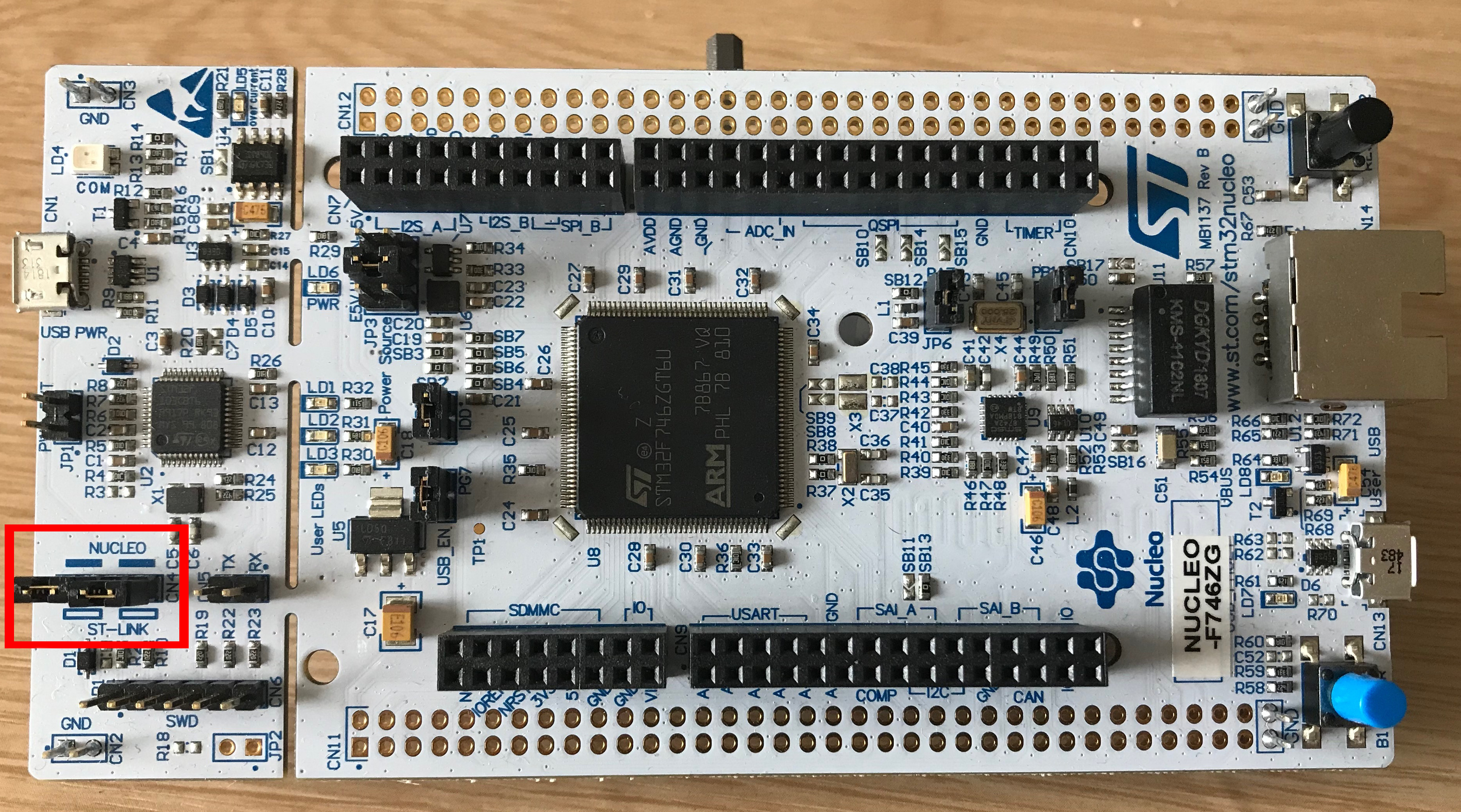
First, make sure the header on the detachable ST-LINK part of the board that I’ve outlined in red above is populated. This header controls whether the USB port on this part of the board will talk directly to the attached debugging microcontroller or use that debugging microcontroller to talk to the main board.
Above the header outlined in red is the Micro USB port that we need to connect to our computer. Once it’s been connected up, you need to run OpenOCD to test connectivity to the board. The output will differ because we’re using different hardware, but it shouldn’t look too different to the output given in the book. The command you need to run for this board is:
$ openocd -f interface/stlink-v2-1.cfg -f target/stm32f7x.cfg
I started with the traditional “Hello, World!” program, but I don’t have a screen connected to this board and attaching one and getting text rendering to it would defeat the point of starting with something simple. So instead I made the board print a “Hello, World!” message to the debugger’s console instead. This uses a mechanism called Semi-hosting, which allows the microcontroller on our board to use the I/O capabilities of the host running the debugger. It’s a pretty slow way of streaming output to the host computer, but it’s simple so it’s ideal for what I want to start with.
There’s a great Cargo template for Cortex-M applications maintained by the Cortex-M subteam of the Embedded Working Group called cortex-m-quickstart. There are instructions in the project’s readme on how to use the template and what you need to edit to make the project build for your specific microcontroller, so I won’t repeat them here. The values you need to follow those instructions can be found in the documentation I mentioned earlier.
I’m using an STM32F746ZG microcontroller, which according to page 1 of the MCU datasheet is based on an ARM Cortex-M7 with a Floating Point Unit (FPU). We can refer to page 8 of the development board user manual to decode the model name of the microcontroller which will tell us how much embedded flash memory it contains. The last digit of the product code is a ‘G’, which corresponds to 1 Mbyte of flash memory.
The MCU reference manual contains a memory map on page 69, which is how I determined where the embedded flash and RAM are located. This diagram looks quite complicated at first, but it’s mapping an entire 4Gbyte address space to all of the various types of RAM, embedded flash, peripherals and I/O ports available on our board, which is an awful lot of information to convey. I was interested in SRAM1 and the Flash Memory on the AXIM interface. The memory map indicated that the Flash Memory is also available on the ITCM interface. The System Architecture section of the MCU reference manual explains that this is “Instruction Tightly Coupled Memory”, which is for specialised use and not suitable for what I needed.
The memory map shows that the SRAM1 address space starts at 0x2001 0000 and that the embedded flash on the interface we want to use starts at 0x0800 0000.
Ideally, I want to be able to send my program to the board and start it under a debugging session without much messing around, so I can quickly test changes. This can be achieved by opening .cargo/config and uncommenting the appropriate line near the start of the file that corresponds to the name your platform uses for the ARM GDB program. For me, this was runner = "arm-none-eabi-gdb -q -x openocd.gdb". Once I’d done this, all I needed to run was cargo run and I was in business!
With all that setup, it’s time to run some actual code on the board! For my “Hello, World!” using semihosting, check My github examples repo. To run this on the board, I ran sudo openocd in the root of the project (where the OpenOCD config is) and cargo run in a second terminal. This will start a GDB session with the program paused, so hit ‘c’ to continue execution. The “Hello, World!” should appear in the OpenOCD terminal.
This post covered how to get an environment setup for developing embedded software using Rust, using the Cortex-M-Quickstart project template, finding useful information about the board from the vast amount of documentation and running some actual code on the board. Next time, I’ll talk about how to use some of the peripherals available to control some LEDs.